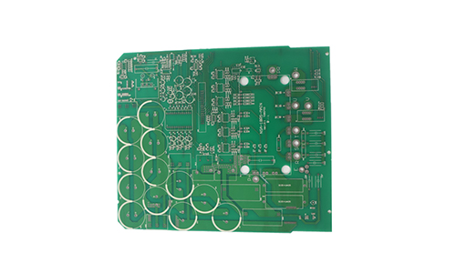
The double-sided low-power PCB circuit board adopts a double-layer structure design, and components can be wired and soldered on both sides.
Double-Sided Low Power PCB Circuit Board Product Introduction
The double-sided low-power PCB circuit board adopts a double-layer structure design, and components can be wired and soldered on both sides. Through reasonable circuit design and high-quality manufacturing process, the stable operation of low-power electronic equipment is ensured.

1. Product Features
1.1 High cost-effectiveness
Compared with multi-layer PCB, the double-sided PCB circuit board has a lower manufacturing cost and is suitable for low-power and low-cost electronic products.
1.2 Good electrical performance
The use of high-quality materials and precise wiring design provides good electrical performance and ensures the stable operation of the circuit.
1.3 Flexible design
The double-sided design allows wiring and soldering of components on both sides, which improves the flexibility and space utilization of circuit design.
1.4 High reliability
The use of high-quality substrates and advanced manufacturing processes ensures the reliability of PCBs in various environments.
1.5 Easy maintenance
The double-sided PCB circuit board has a simple structure, which is easy to detect and repair, and reduces maintenance costs.
2. Technical Parameters
| Number of layers | 2 | Minimum line width and line spacing | 0.3/0.3mm |
| Board thickness | 1.6mm | Minimum aperture | 0.3 |
| Board material | KB-6160 | Surface treatment | lead-free tin spraying |
| Copper thickness | 2/2oz | Process points | / |
3. Application Areas
3.1 Consumer electronics
Used for circuit design of consumer electronic products such as smartphones, tablets, smart watches, etc., providing efficient and reliable power supply solutions.
3.2 Household appliances
Used for circuit control and power transmission of household appliances such as TVs, refrigerators, washing machines, etc., to ensure stable operation of the equipment.
3.3 Medical equipment
Used for circuit design of medical equipment such as blood pressure monitors and electrocardiographs, providing high-reliability power supply solutions.
3.4 Industrial control
Used for circuit design of industrial control equipment to meet the needs of low power and high reliability.
3.5 Automotive electronics
Used for circuit design of automotive electronic equipment such as car audio and navigation systems, providing stable power supply solutions.
4. Manufacturing Process
4.1 Circuit design
Use EDA tools to design and route circuits to ensure the rationality and reliability of the circuit.
4.2 Material selection
Select high-quality substrates and copper foils to ensure the performance and reliability of the PCB.
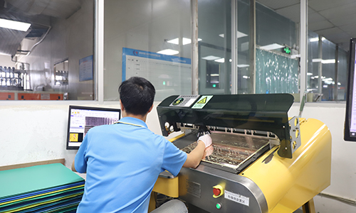
4.3 Etching
Etch to form circuit patterns.
4.4 Vias
Drill and electroplate to form vias.
4.5 Surface treatment
Perform surface treatment such as HASL, ENIG, etc. to improve the welding performance and corrosion resistance of the PCB.
4.6 Welding
Weld components to complete assembly.
4.7 Testing
Perform electrical and functional tests to ensure product quality.
5. Quality control
5.1 Raw material inspection
Ensure that the quality of the substrate and copper foil meets the standards.
5.2 Manufacturing process control
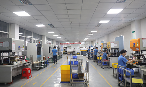
Strictly control each process to ensure product consistency and reliability.
5.3 Finished product testing
Perform electrical performance tests, functional tests, and environmental tests to ensure that the product meets the design requirements.
 |
 |
6. Conclusion
Double-sided low-power PCB circuit boards are widely used in various low-power electronic devices due to their high cost-effectiveness, good electrical performance and high reliability. Through reasonable design and strict manufacturing process, efficient and reliable power solutions can be achieved to meet the needs of diverse electronic products.
I hope this product introduction will be helpful to you!
FAQ
Q: What files are used in PCB production?
A: PCB production requires Gerber files and PCB manufacturing specifications, such as the required substrate material, finished thickness, copper layer thickness, solder mask color, and design layout requirements.
Q: When can I get a quotation after I provide Gerber, product process requirements?
A: Our sales staff will give you a quotation within 1 hour.
Q: How to solve the common overheating problems when using power PCB ?
A: The key is to introduce heat dissipation design and or choose high quality materials. For example: EMC, TUC, Rogers and other companies to provide the board.
Q: How long does it generally take to deliver HDI high-frequency PCB?
A: We have raw material inventory (such as RO4350B, RO4003C, etc.), and our fastest delivery time can be 3-5 days.