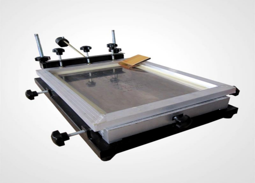

The SMT stencil manufacturing process specification includes several critical components and steps to ensure the quality and accuracy of the stencil. Now let’s learn about the key elements involved in the production of SMT stencils:
1. Frame: The frame can be either removable or fixed. Removable frames allow for the reuse of the frame by changing the stencil sheet, while fixed frames use adhesive to bond the mesh to the frame. The frame size is determined by the requirements of the solder paste printer, with common sizes such as 29" x 29" (736 x 736 mm) for machines like the DEK 265 and MPM UP3000 models. The frame material is typically aluminum alloy, with a thickness of 40 ± 3mm and a flatness tolerance of no more than 1.5mm .
2. Mesh: The mesh is used to secure the stencil sheet and frame and can be made of stainless steel wire or high polymer polyester. Stainless steel wire mesh is commonly used with a mesh count of around 100, providing stable and sufficient tension. Polyester mesh is also used for its durability and resistance to deformation .
3. Stencil Sheet: The stencil sheet, or foil, is made from materials such as stainless steel, with thicknesses ranging from 0.08mm to 0.3mm (4-12 MIL). The choice of material and thickness is crucial for the stencil's durability, corrosion resistance, ductility, and thermal expansion coefficient, which directly affect the stencil's service life .
4. Adhesive: The adhesive used to bond the frame and stencil sheet plays a significant role in the stencil's performance. It must maintain a strong bond and resist various stencil cleaning solvents without reacting chemically .
5. Stencil Making Process: The stencil making process can involve different techniques such as laser cutting, chemical etching, or electroforming. Laser cutting is a common method that uses high-energy lasers to precision-cut the stencil sheet, followed by electropolishing to reduce the roughness of the hole walls. This method is suitable for fine-pitch devices and offers a high level of accuracy and cleanliness .
6. Stencil Design: The design of the stencil includes the aperture size, which is crucial for controlling the quality of the solder paste printing process. The aperture size is typically slightly smaller than the pad size on the PCB, especially for fine-pitch devices, to prevent issues like solder balls or bridging .
7. Stencil Tension: The tension of the stencil is important for its performance and is usually measured at nine points on the stencil sheet. The tension should be within a specified range, such as greater than or equal to 40N/cm for new stencil sheets, and replaced if it falls below 32N/cm .
8. Mark Points: Mark points on the stencil are essential for accurate alignment with the PCB during the printing process. The number and position of these points should correspond to the mark points on the PCB .
9. Stencil Thickness Selection: The thickness of the stencil sheet is chosen based on the smallest pad pitch and component size on the PCB. Thinner stencils are used for finer pitches, while thicker stencils are used for larger pitches .
In summary, the guidelines for stencil usage can be encapsulated in the following points:
1. The apertures are naturally trapezoidal, with the upper aperture typically being 1 to 5mil larger than the lower one, which facilitates the release of solder paste.
2. The aperture size tolerance is about 0.3 to 0.5mil, with a positioning accuracy of less than 0.12mil.
3. The cost is higher than chemical etching but lower than electroformed stencils.
4. The hole walls are not as smooth as those of electroformed templates.
5. The common thickness for template fabrication is 0.12 to 0.3mm.
6. It is generally recommended for printing with component pitch values of 20mil or smaller.
By adhering to these specifications and processes, Sanxis can ensure that the SMT stencils are of high quality and suitable for precise and reliable solder paste printing.
In the next news article, we will introduce the design requirements for the fabrication of SMT stencils.