
Let’s continue learn about the common terms of high speed PCB.
1. Reliability
Whenever current flows through a conductor, it generates a magnetic field around the conductor. Conversely, when a magnetic field passes through a conductor, it induces a voltage within that conductor. Therefore, all conductors in a circuit (usually traces on a PCB) can generate and receive electromagnetic interference, which may cause distortion of the signals being transmitted along the traces.
Each track on a PCB can also be seen as a small radio antenna, capable of generating and receiving radio signals, which may distort the signal carried by the track.
2. Impedance
As mentioned earlier, electrical signals are not instantaneous; they actually propagate in the form of waves within the conductor. In the 3GHz / 30cm trace example, there are 3 waves (crests and troughs) within the conductor at any given time.
Waves are affected by various phenomena, the most important of which for us is "reflection."
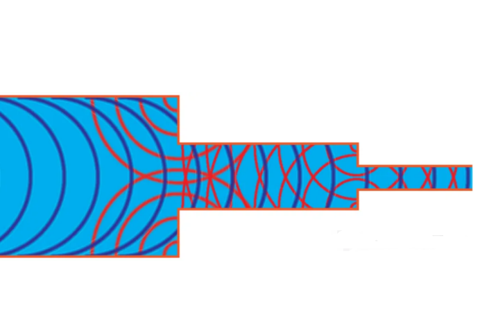
Imagine our conductor as a canal filled with water. Waves are generated at one end of the channel and travel along the channel (at nearly the speed of light) to the other end. The channel is originally 100cm wide, but at some point, it suddenly narrows to only 1cm wide. When our wave reaches the suddenly narrowed part (essentially a wall with a small gap), most of the wave will be reflected back towards the narrow part (the wall) and towards the transmitter. (As you can see clearly in the cover picture)
If there are multiple narrow parts in the canal, there will be multiple reflections, interfering with the signal, and most of the signal's energy will not reach the receiver (or at least not at the correct time). Therefore, it is important that the width/height of the channel remains as constant as possible along its length to avoid reflections.
The narrow parts mentioned above are impedances, which are a function of the conductor's resistance, capacitance, and inductance. For high-speed designs, we want the impedance along the trace to remain as consistent as possible throughout its length. Another thing to consider, especially in bus topologies, is that we want to stop the wave at the receiver, rather than have it reflect again.
This is typically achieved through the use of terminating resistors, which absorb the energy of the end wave (such as in RS485 bus).
If you want to know more about out high speed PCB products, welcome to take orders with us.