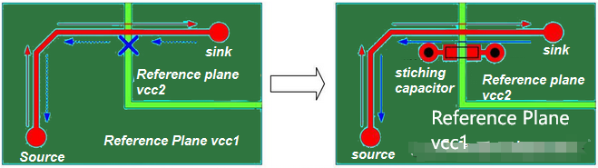
When routing signals across two different reference planes, it is necessary to incorporate stitch capacitors. Stitch capacitors allow the return current to transfer from one reference plane to another. Capacitors should be placed close to the signal path to minimize the distance between the forward path and the return path. Typically, stitch capacitors range between 10nF and 100nF.
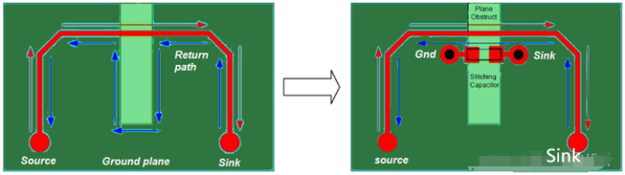
In general, it is essential to avoid plane obstacles and plane slots. If it is necessary to bypass such obstacles, stitch capacitors should be used as shown in the diagram below.
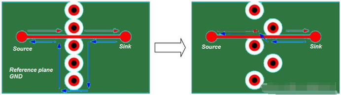
Designers should pay attention to voids in the reference plane when routing high-speed signals. As shown in the diagram, voids in the reference plane are created when vias are placed too close together. Large void areas should be avoided by ensuring there is sufficient spacing between vias. It is best to place fewer ground and power vias to reduce via spacing.
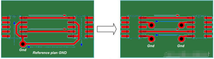
The return path is at the source and sink of the signal. In the diagram below, the design on the left is considered poor. Since there is only one ground via on the source side, the return current cannot be expected to return to the reference ground plane. The return path exists in the ground connection on the top layer. The issue is that the impedance of the signal trace is calculated based on the ground plane, not the ground trace on the top layer. Therefore, ground vias must be placed at both the source and sink ends of the signal to allow the return current to return to the ground plane. As shown on the right side of the diagram below.